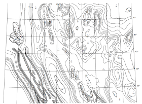
For the designers or owners of individual buildings, or for urban planners or city authorities, the issue is how likely a specific site is to experience earthquake forces of a certain severity. Building design codes adopt one of two alternative procedures for specifying the geographical distribution of design loads:
(1) seismic zonation or
(2) contour mapping of expected ground motion.
(1) seismic zonation or
(2) contour mapping of expected ground motion.
Most national codes of practice use the seismic zonation concept. The country (or region) covered by the code is divided into a small number (usually no more than four or five) of separate source zones, within each of which the lateral loading requirement for earthquake-resistant design is constant, and is specified by a zone coefficient. The zone coefficient relates to the expected peak ground acceleration within a predefined return period, but this information does not need to be known by the designer. The Turkish seismic zonation map (Figure 1) is a typical example. In this code the zone coefficients are 0.1, 0.06, 0.04 and 0.2 for Zones 1, 2, 3 and 4 respectively, corresponding roughly to the peak ground acceleration (as a proportion of the gravitational acceleration g) with a 10% probability of exceedance in 50 years. These coefficients are converted into a response spectrum for design using further coefficients for local soil type and building importance. Similarly, Figure 2 shows seismic zones of Pakistan.
 |
| Figure 1: Seismic zoning map of Turkey |
The advantage of this method for specifying design loads is its simplicity for designers. The zones, although defined from knowledge of regional seismicity, are not given a formal definition in terms of expected ground motion. Their significance derives from the use of the zone coefficient in the formulae in the accompanying code, so they have a semi-legal character, like district boundaries.
 |
| Figure 2: Seismic zoning map of Pakistan |
However, the approach also has disadvantages. One disadvantage is that the seismic zonation is coarse, and is unable to take into account the effects of local features such as fault zones. Another is that only a single parameter is defined, whereas it is now accepted that at least two independently varying parameters are needed to take adequate account of the variations in regional seismicity. These two disadvantages are overcome through the use of contour maps such as those accompanying the 2000 International Building Code. The code specifies that the design loading should be that associated with the maximum credible earthquake (MCE) at the site. Contour maps of the entire United States indicate the values of two key design parameters to be used to construct the design ground motion response spectrum at that site: the spectral acceleration values at 0.2 s and 1.0 s periods. The value of these parameters is derived from the US Geological Survey’s hazard maps which are contour maps of the 0.2 and 1.0 s spectral accelerations with a 10% probability of exceedance in 50 years, but with modifications for some parts of the United States to take account of the effects of known local faulting on design loads, and with variations for different classes of site defined by soil conditions. Figure 3 shows, for example, the MCE ground motion map of a small part of Western United States for the 0.2 s horizontal spectral acceleration (% of g), for Site Class B. Maps such as these represent a considerable step forward in defining appropriate design load coefficients and are likely to become the standard approach for future codes in other countries.
 |
| Figure 3: Maximum considered earthquake ground motion for region 1 of 0.2 sec spectral response acceleration (5 percent of critical damping), site class B |
